Türkçe (Turkish)
 English (İngilizce)
Problem Identification:
High vibration levels observed during the commissioning process of Unit-1 turbine-generator set at a domestic hydroelectric power plant necessitated a critical technical intervention to ensure the safe and sustainable operation of the equipment.
In previous interventions on the unit by different companies, no mechanical surface, balance plane, or accessible area on the vertical shaft architecture where a correction mass could be applied was identified; the work were left unfinished, and the unit was delivered unresolved.
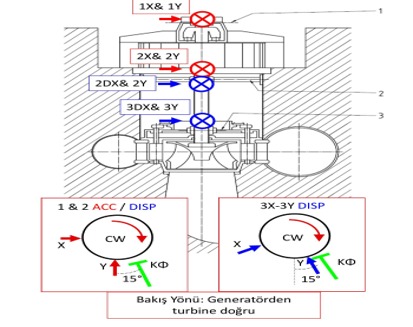
At this point, support was requested from the technical team of the Resonance Institute. They went to the site, integrated a multi-channel TWave-T8 analyzer into the equipment’s existing monitoring system, and implemented a rotordynamic measurement procedure specific to the vertical shaft hydroelectric unit. Using accelerometers and relative shaft displacement sensors, comprehensive data was collected through full spectrum, shaft centerline, and orbit analyses.
Diagnosis: Severe Imbalance
1X Dominant Component at Synchronous Frequency
-
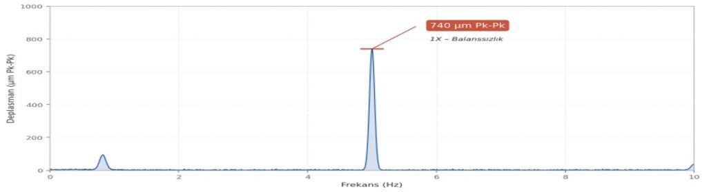
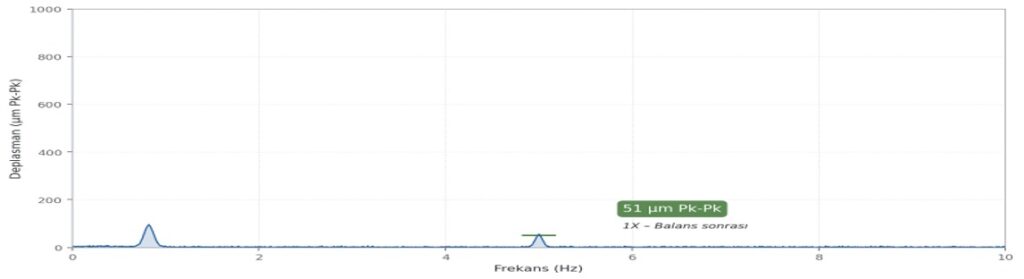
In multi-channel vibration measurements performed under a 7 MW load, a dominant vibration character was detected in the 1X component of the system's synchronous operating frequency. At the P7 measurement point of the relative shaft displacement sensor located in the turbine guide bearing, a component reaching 740 µm Pk-Pk amplitude at the 1X frequency was revealed.
-
When the dominant 1X component, constant phase angle, and amplitude correlation with load variation are evaluated together, it is clearly confirmed that there is a classical rotordynamic imbalance problem in the system.

Engineering Solution
Special Design Balance Disc
-
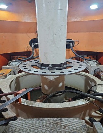
The absence of a standard correction plane in the existing vertical shaft geometry has made it necessary to address the problem not only through measurement but also through mechanical design. Regarding the problem of not being able to perform the balancing operation on the lower turbine impeller or the operation taking too long, a special steel balancing disc concept was proposed by the Resonance Institute engineering team to eliminate the imbalance on the impeller side. In line with this proposal, the design, manufacturing and assembly of the disc that perfectly fits the shaft, based on the equipment geometry and shaft dynamic characteristics, was carried out by the customer. Thanks to this developed solution, the process of shedding weight onto the turbine was reduced from 4 hours to 15 minutes, resulting in significant time savings.
-
Vector Angle Holes
A phase-accurate correction ground compatible with modal balancing procedures, calibrated according to the rotor reference angle, with multiple correction holes.
Full Mechanical Integration
Manufactured in a two-part clamp geometry, the disc is rigidly integrated into the shaft with a tight-fitting connection; the risk of slippage under dynamic conditions is eliminated.
Ease of Operational Access
The disc position is designed to facilitate weight addition/removal interventions during fine-tuning iterations after commissioning for the operator.
Result: 93% Recovery
Before and After Balancing Comparison

-
At the measurement points on the generator side, no negative interaction related to the balancing process was observed; the effect remained localized to the modal response on the turbine side as designed. This behavior confirmed with field data that the balance disc position and correction angles are correctly aligned with the modal effect vector.
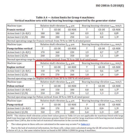
Appendix 1: ISO 20816-5 Vibration Standards